After a long time, I am back again.
These days I was busy with my studies and not getting time to look into the project.
For now this is on hold and will start back in December.
Wednesday, November 11, 2009
Saturday, October 24, 2009
BAD News.
The Acrylic I bought, after smoothing edges become too small to be used. I bout the acrylic just 1.5' larger then the LCD but after a huge process of smoothing (which included cutting some part of the edges as there were too much scratch on that side) the sheet become just 1/2' larger then the LCD and when I tried to put wooden frame (containing LEDs) the LCD was not getting in the Frame. A loss of 350 INR of Frame, 75 INR of Acrylic and lots of labor + time. More over the New acrylic cost me 600 INR, but this time I bought 6mm the 8mm one was costing more then 1000 INR so I just bought 6mm one.
Now again lots of labor to smoother the edges and then testing.
Now again lots of labor to smoother the edges and then testing.
Friday, October 23, 2009
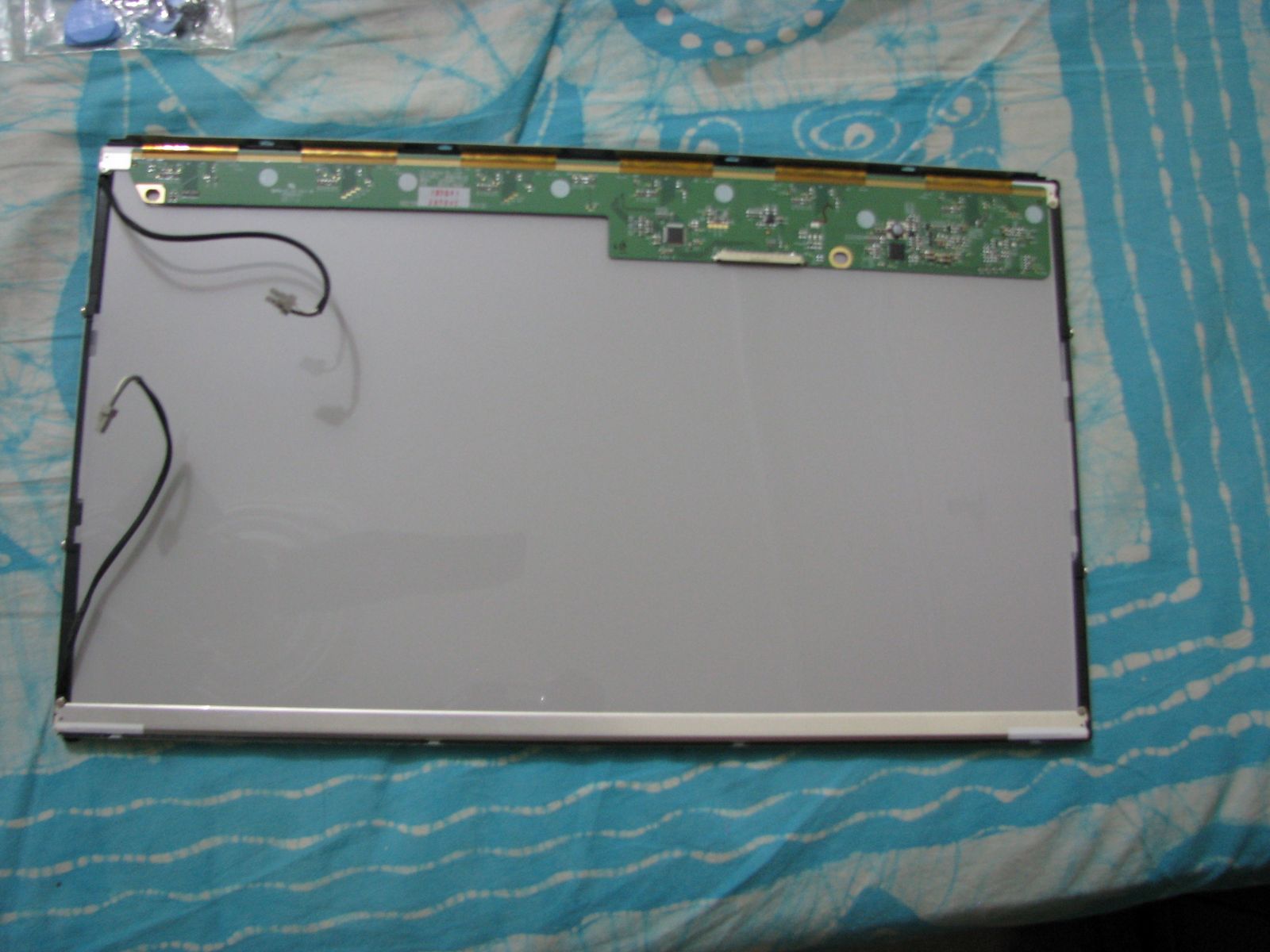
Disassembling LCD
Today, I dis-assembled my LCD. Although Pictures are telling more then me, but I will try my best to explain.
 The LCD as I bought it.
The back of it.

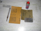
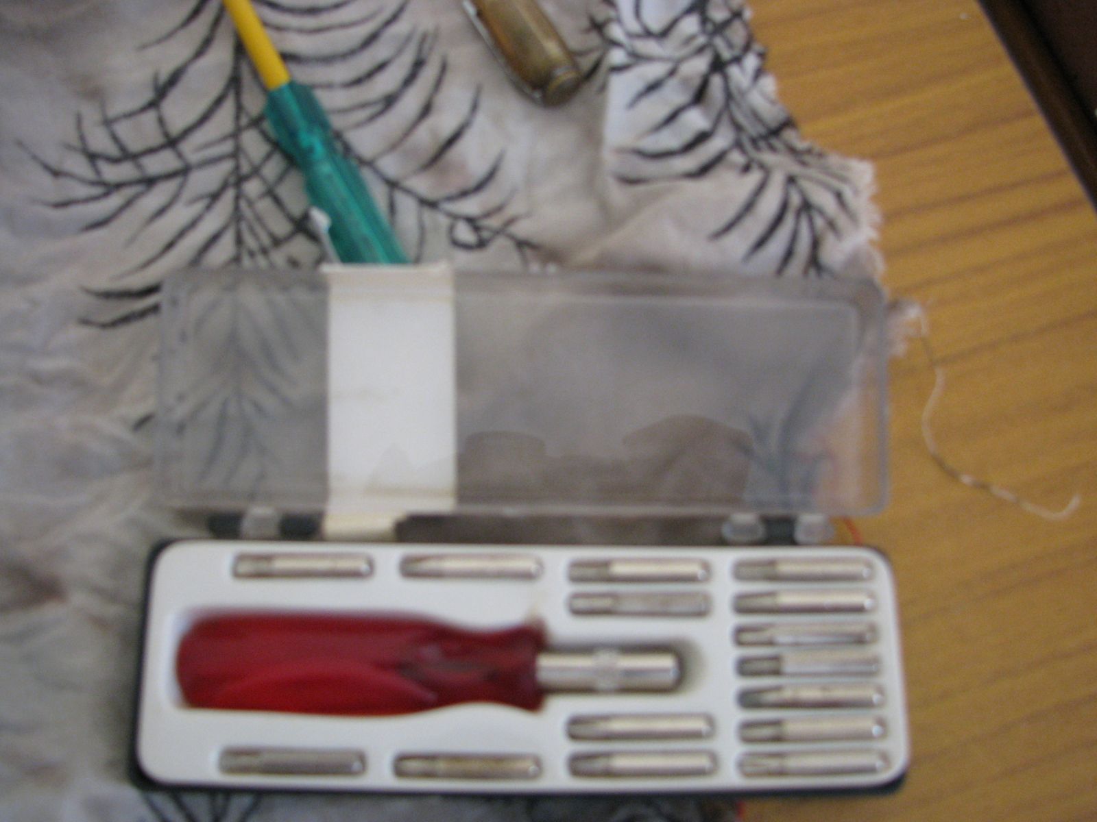 The tools, a small screw driver and a set of mobile repairing bits. I used it because these are very handy and I am expacting some small/diamond screws.
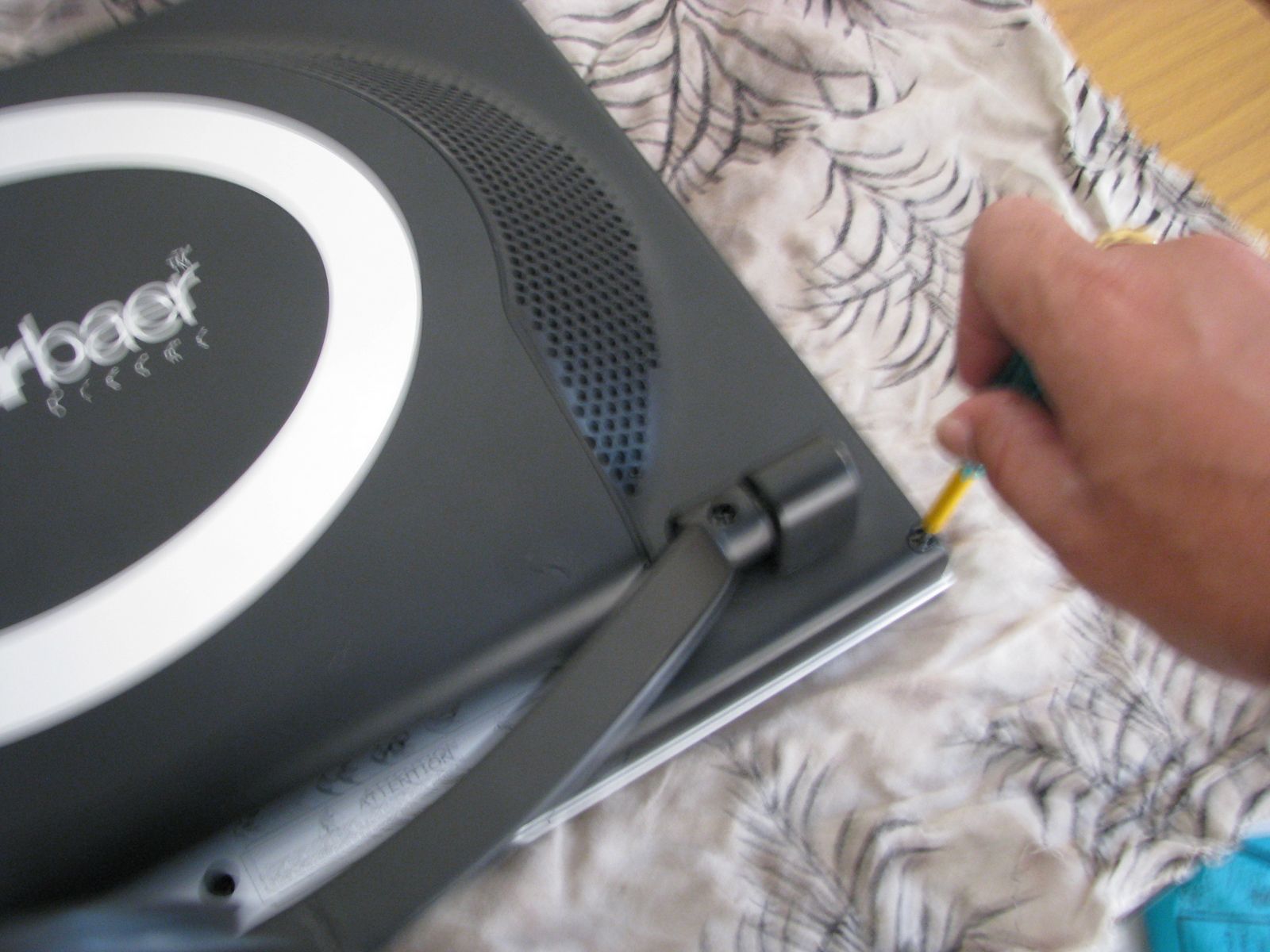
Unscrew the back panal.
Use this unknown tool to pull apart the panal which are locked with latches.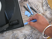

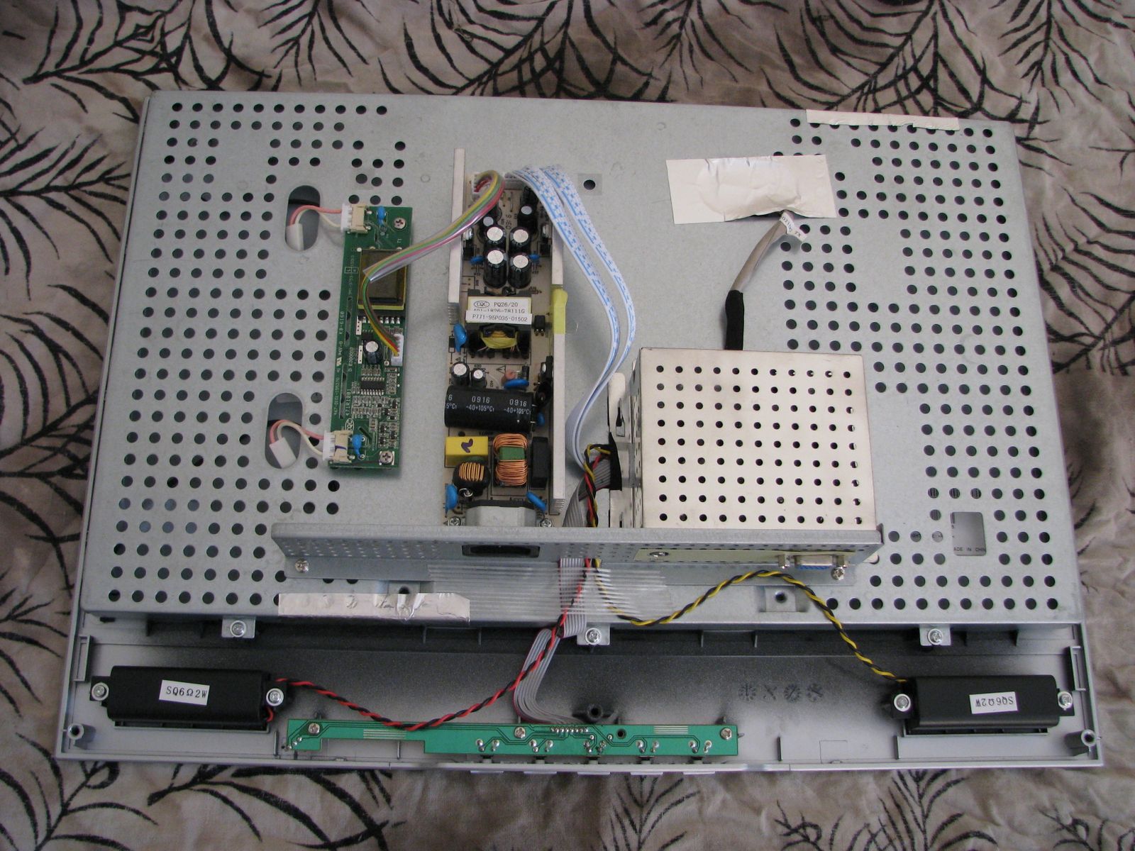
Here is the whole thing inside.
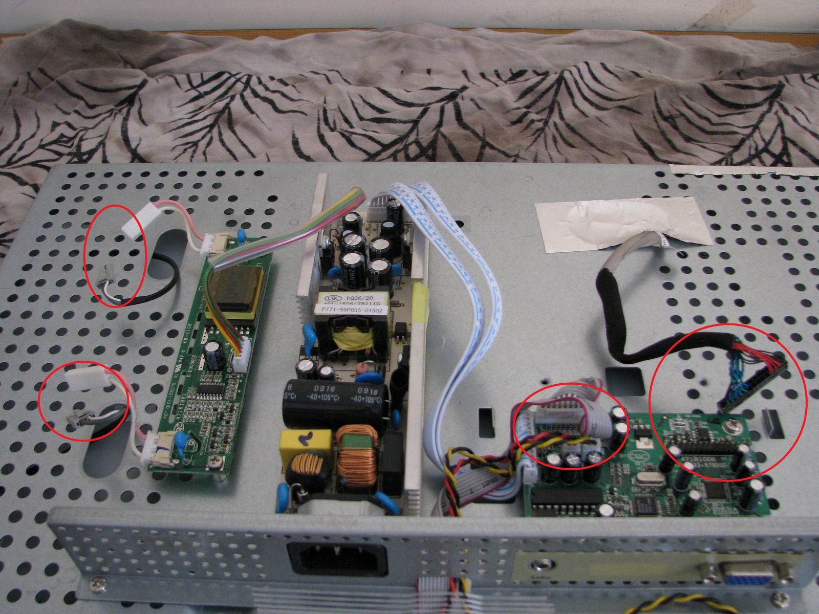
Remove the cables (Marked in circle) so that the front panal could be removed.
Yes, the front panal is also removed, now we need to un-screw some more screws so that the casing could be removed.
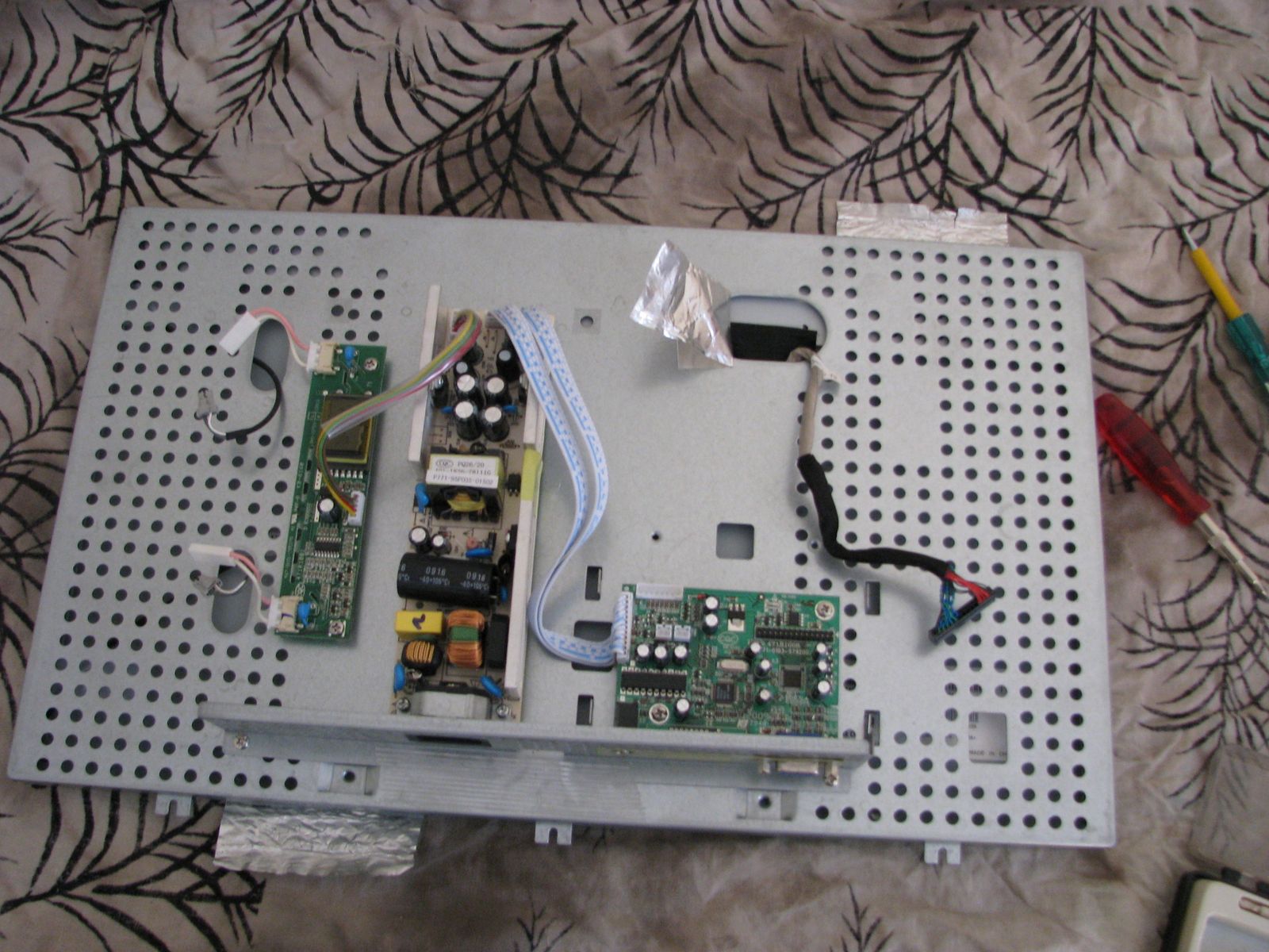
Pull apart the back of the casing.

The raw LCD from back.
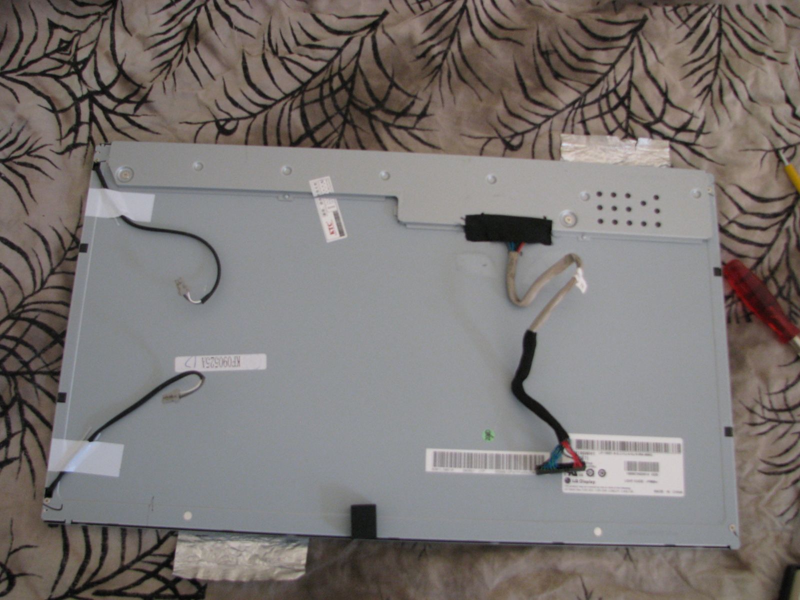
Unscrew the back and remove the stickers that were put to support the cables
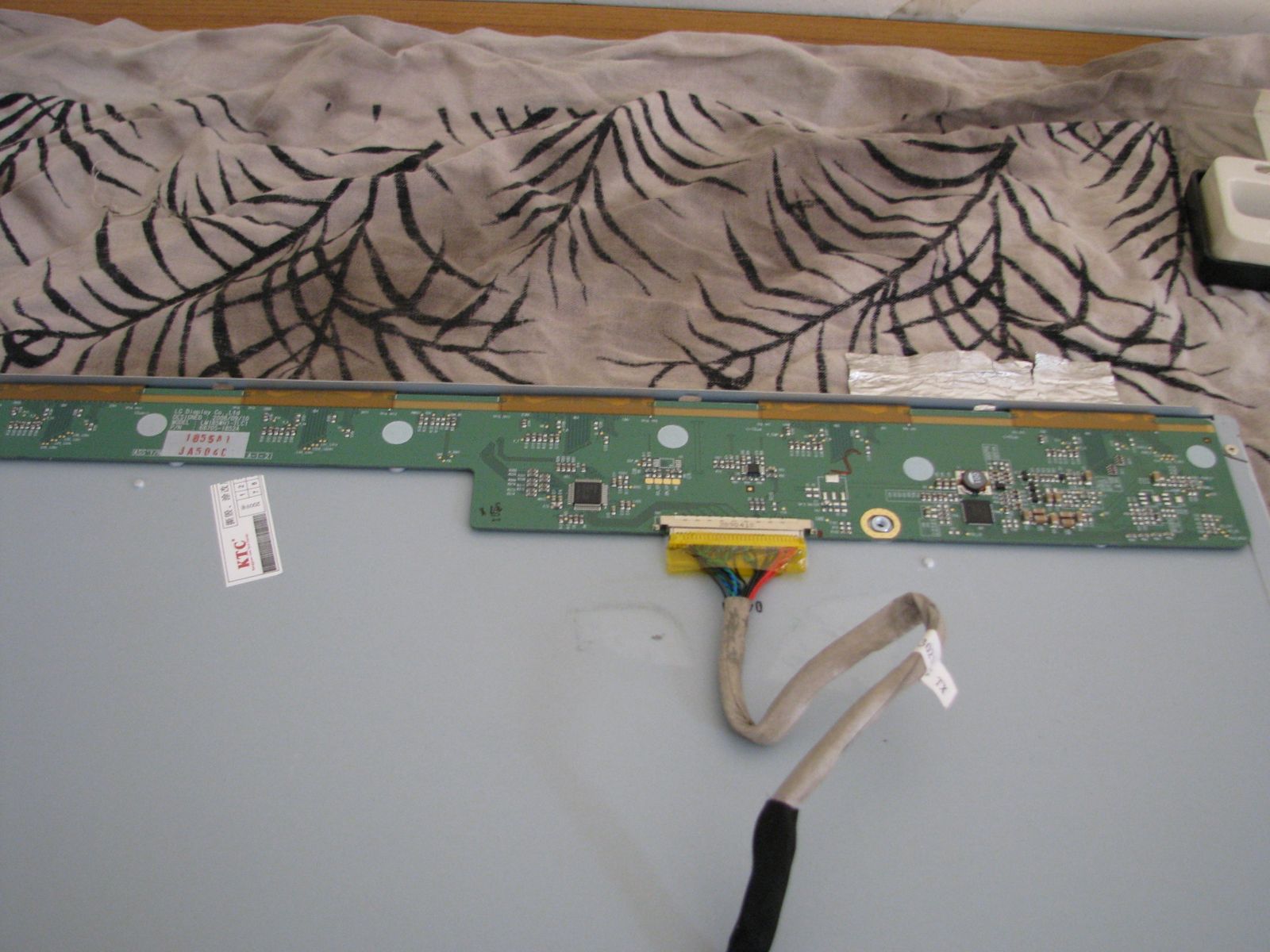
Ok, now pull apart the back and the sides. Every thing isie will be now in your hands. Below is the LCD and the endlighten.

LCD.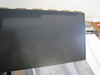

First Opaque plastic sheet.
Second Opaque plastic sheet.
The Endlighten.
The tube bulbs.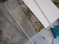
The diffueser. This was sticked to the endlighten.
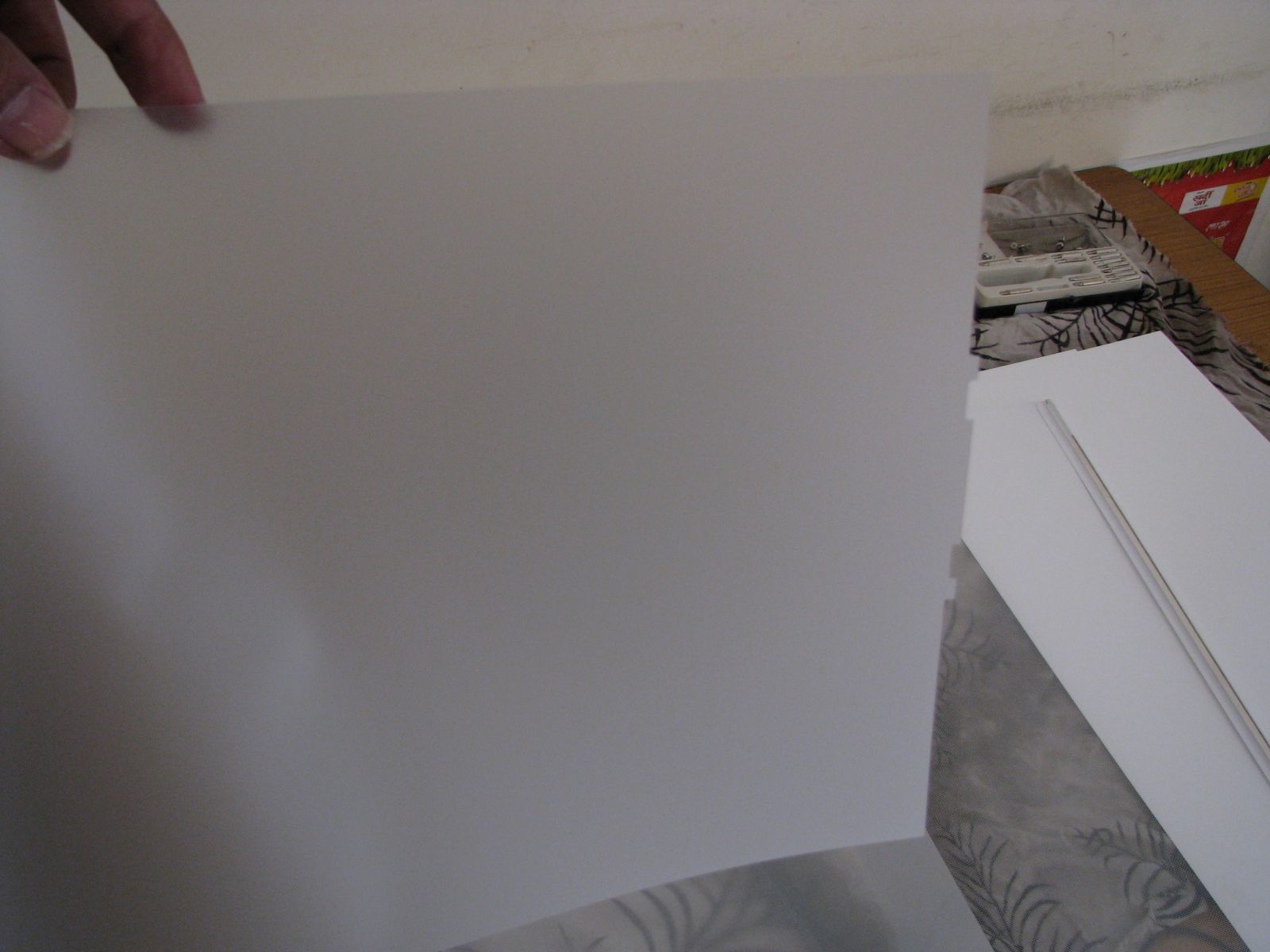
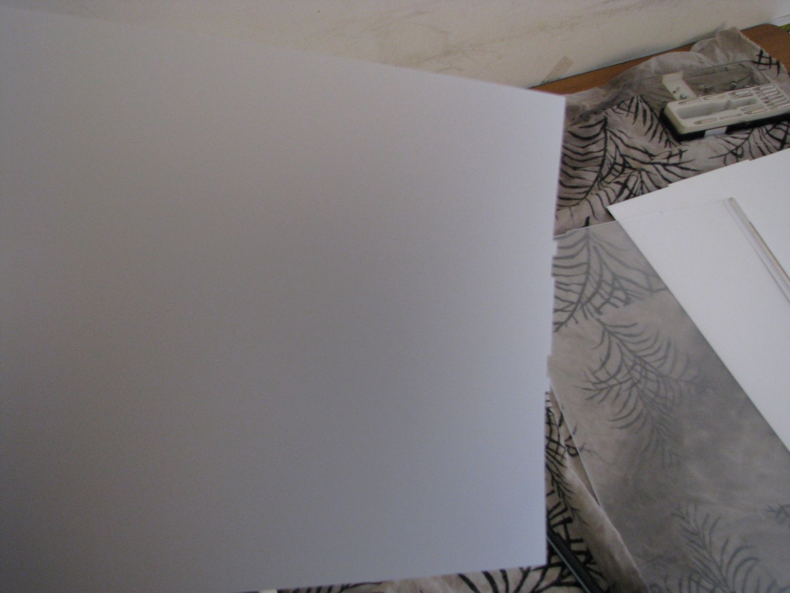
I just removed diffueser replaced it with the second opaque sheet. Now I put back everything back, without the diffuser and the back steel body. This thing is ready to go below my Acrylic.
See it is not transparent but I think IR can pass through it.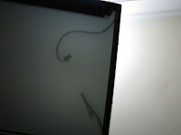

Now I will continue with putting the LCD and Acrylic togather and see wha happens.
Thursday, October 22, 2009
Technology.
While I am waiting for a wooden frame from carpenter, there is no much hardware grow since Tuesday, let me tell you about the technology I am using for the table.
Microsoft surface used DI (Direct illumination) technique in his table in which IR rays are passed from below the projection surface (the screen which you touch). When there is some object, including human touch, on the glass IR is reflected back and is being captured by array of IR cameras which is further being processed by vision system and interpreted as touch.
Having advantage of Object recognition (termed as tag recognition) this technology cannot be used when you are using LCD for your table. Reason, in this method the IR has to pass the LCD 2 times which makes then week while reaching back to camera.
The best approaches known for LCD based Table are LLP (Light Laser Plane) and FTIR (Frustrated Total Internal Reflection).
In LLP method a laser Light is being spread over the screen and when some object is placed it is illuminated and is captured by camera. Being best method the draw backs are Laser can be harmful if by mishap is penetrating to cornea (there may be some other health issues but I have not researched through them. The other drawback is the corners or the edges of the screen has to be protruded to accommodate laser light which is not a good design for coffee table or if you are needing a plane surface.
So I have left with FTIR method. The major drawback of this method is it could not recognize tags or objects. Hmmm, is it really needed for your first project? The other draw back is, it asks much labor (at least I found that) and specific material.
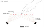
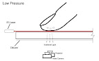
In this method IR is passed through edges of Acrylic, due to specific Total Internal Reflection property of Acrylic IR rays cannot move out of the sheet and when touch is made the IR is frustrated and reflected to Camera below. To achieve better reflection either you have to put some compliant surface over the sheet of you need wet hands (via water or oil). I may use Silicon spray for compliant surface.
This is the Surface part now comes the display. A projector or a LCD can be used to display contents on surface. Microsoft uses Projector which will cost much more for a RnD stuff so I am using a 18.5 LCD screen.
Below the projection surface a IR camera (or a modified camera to see IR) is needed to track the reflected IRs.
This is the hardware scheme, now the software. The tracker software tracks images reflected back from surface and creates usable images and then the contact points are converted into blob (Blob is a image created by the touch reflection) then these blobs are converted into messages which can be used by client applications do what they want. Most common tracker software are CCV, touchlib, Vision system etc.
Microsoft surface his own vision system software to track images and convert them into windows messages and tags. Microsoft Surface SDK utilize these messages (and tags) to create application. If you don't have windows 7 or you don't want Microsoft surface solution then you can use CCV, touchlib etc. to track IR images and create blobs from them. If you want to use Microsoft surface software (which is hell hard to find) you must have a best configuration system.
Thanks to Daniel D for creating HID drivers that can be used to send messages and now we can use Microsoft Surface without his Vision system (I am sure Daniel will come up with a solution for Tag recognition).
Microsoft surface used DI (Direct illumination) technique in his table in which IR rays are passed from below the projection surface (the screen which you touch). When there is some object, including human touch, on the glass IR is reflected back and is being captured by array of IR cameras which is further being processed by vision system and interpreted as touch.
 |
Having advantage of Object recognition (termed as tag recognition) this technology cannot be used when you are using LCD for your table. Reason, in this method the IR has to pass the LCD 2 times which makes then week while reaching back to camera.
The best approaches known for LCD based Table are LLP (Light Laser Plane) and FTIR (Frustrated Total Internal Reflection).
In LLP method a laser Light is being spread over the screen and when some object is placed it is illuminated and is captured by camera. Being best method the draw backs are Laser can be harmful if by mishap is penetrating to cornea (there may be some other health issues but I have not researched through them. The other drawback is the corners or the edges of the screen has to be protruded to accommodate laser light which is not a good design for coffee table or if you are needing a plane surface.
 |
So I have left with FTIR method. The major drawback of this method is it could not recognize tags or objects. Hmmm, is it really needed for your first project? The other draw back is, it asks much labor (at least I found that) and specific material.
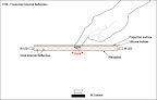 |
In this method IR is passed through edges of Acrylic, due to specific Total Internal Reflection property of Acrylic IR rays cannot move out of the sheet and when touch is made the IR is frustrated and reflected to Camera below. To achieve better reflection either you have to put some compliant surface over the sheet of you need wet hands (via water or oil). I may use Silicon spray for compliant surface.
This is the Surface part now comes the display. A projector or a LCD can be used to display contents on surface. Microsoft uses Projector which will cost much more for a RnD stuff so I am using a 18.5 LCD screen.
Below the projection surface a IR camera (or a modified camera to see IR) is needed to track the reflected IRs.
This is the hardware scheme, now the software. The tracker software tracks images reflected back from surface and creates usable images and then the contact points are converted into blob (Blob is a image created by the touch reflection) then these blobs are converted into messages which can be used by client applications do what they want. Most common tracker software are CCV, touchlib, Vision system etc.
Microsoft surface his own vision system software to track images and convert them into windows messages and tags. Microsoft Surface SDK utilize these messages (and tags) to create application. If you don't have windows 7 or you don't want Microsoft surface solution then you can use CCV, touchlib etc. to track IR images and create blobs from them. If you want to use Microsoft surface software (which is hell hard to find) you must have a best configuration system.
Thanks to Daniel D for creating HID drivers that can be used to send messages and now we can use Microsoft Surface without his Vision system (I am sure Daniel will come up with a solution for Tag recognition).
Wednesday, October 21, 2009
Testing Acrylic for Blobs
I am feeling lucky that I got smooth edges, now comes testing of acrylic for getting blobs.
I prepared 4 series of 10 IR LEDs in each series, the wiring diagram goes as below
These rail of LEDs are pasted over the edges of the Acrylic and connected to 18.5v Laptop power adapter. You will see that I used 56ohm resistor instead of 68ohm mentioned in the diagram, actually I could not find 68 one any nearby I will try to gather one while completing the table.
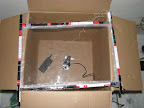
I took a box (which is a outer box of the geyser I bought recently) around 15 inch in depth, kept the modified webcam in the center of the box.
I think I did not tell you about modifying the webcam, I just unscrewed the Lens and removed IR filter then covered the lens with floppy film (I may need to replace with some other IR band pass filter).
On the box with webcam below I put the acrylic screen connected every thing as needed (I mean power supply and the webcam).
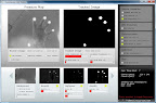
Now comes testing for blob. Launch CCV and tried to find blobs. As I done some previous testing with MiniMT also my ccv got corrupted this needed deleting of config.xml.
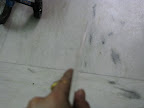
At first I can see my whole hand but no blobs, after applying some coconut oil and adjusting through camera properties (like gamma correction, white balancing etc. just hit and tried) I can see some blobs but these are not mature enough to port so I applied last thing, some water on my fingers and VOILA there are blobs detected Cute and Sexy. see below.
Whats next:
- Arrange wooden beeds to fix LEDs and the acrylic.
- Arrange Complient surface (I have seen Silicon spray which may be used.)
- Arrange mirror as the box is too small for whole screen to capture, right now the cam is seeing only 50% area, I could not increase depth (as I need to fit this assembly in my daughter's study table).
- Major part, disassembling LCD.
I prepared 4 series of 10 IR LEDs in each series, the wiring diagram goes as below
 |
These rail of LEDs are pasted over the edges of the Acrylic and connected to 18.5v Laptop power adapter. You will see that I used 56ohm resistor instead of 68ohm mentioned in the diagram, actually I could not find 68 one any nearby I will try to gather one while completing the table.
I took a box (which is a outer box of the geyser I bought recently) around 15 inch in depth, kept the modified webcam in the center of the box.
 |
I think I did not tell you about modifying the webcam, I just unscrewed the Lens and removed IR filter then covered the lens with floppy film (I may need to replace with some other IR band pass filter).
 |
On the box with webcam below I put the acrylic screen connected every thing as needed (I mean power supply and the webcam).
Now comes testing for blob. Launch CCV and tried to find blobs. As I done some previous testing with MiniMT also my ccv got corrupted this needed deleting of config.xml.
At first I can see my whole hand but no blobs, after applying some coconut oil and adjusting through camera properties (like gamma correction, white balancing etc. just hit and tried) I can see some blobs but these are not mature enough to port so I applied last thing, some water on my fingers and VOILA there are blobs detected Cute and Sexy. see below.
 |
Whats next:
- Arrange wooden beeds to fix LEDs and the acrylic.
- Arrange Complient surface (I have seen Silicon spray which may be used.)
- Arrange mirror as the box is too small for whole screen to capture, right now the cam is seeing only 50% area, I could not increase depth (as I need to fit this assembly in my daughter's study table).
- Major part, disassembling LCD.
Preparing Acrylic Edges.
Over the Week, I have been working on preparing the edges of the Acrylic sheet. The sheet I got was some what uneven and being noob it cost me much time to clear the edges (Also could not devote much time for the project due to diwali).
My first step was to make the Edges even for This I used knife to cut out all the protruding edges.
After cutting out edges I filed the edges with a file around 25 frictions at each place.
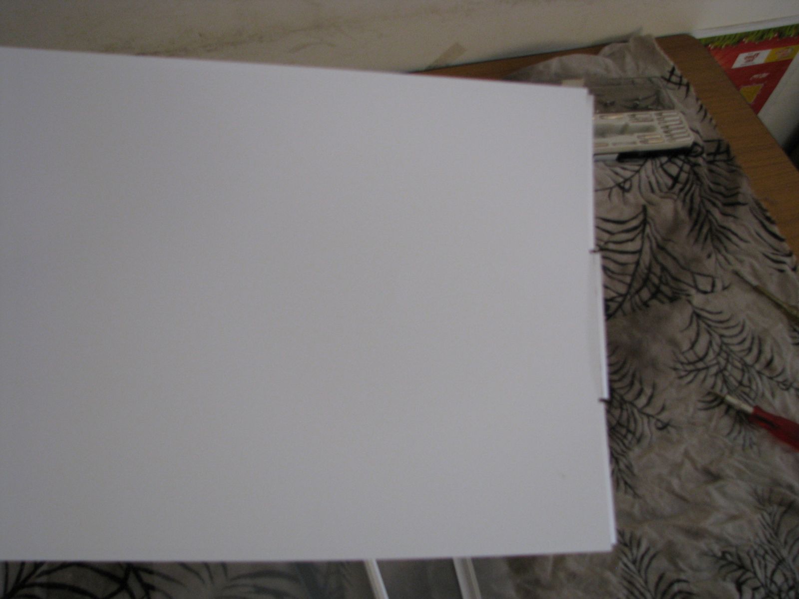
The first finish edge look somewhat like this.
Once filing on all surfaces is done, I used emery stone then 150 grit sand paper then 1500 grit sand paper.
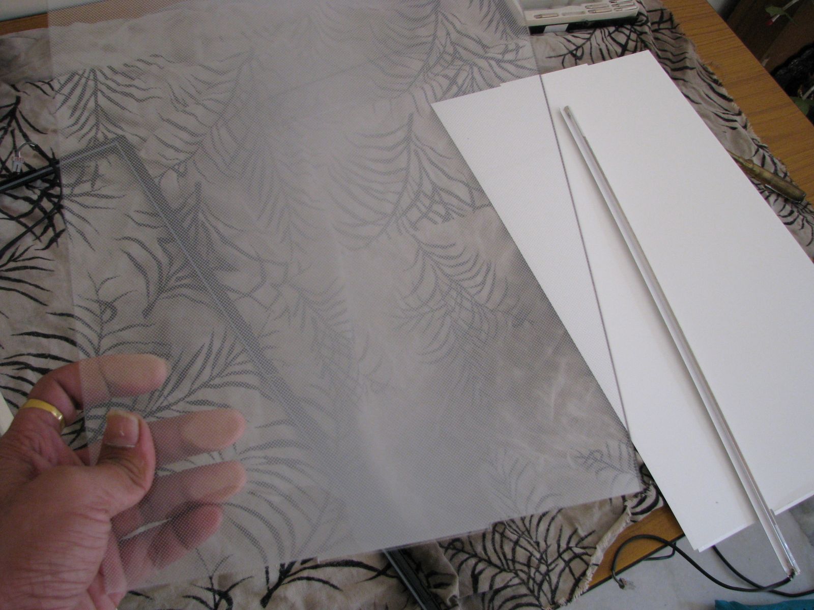
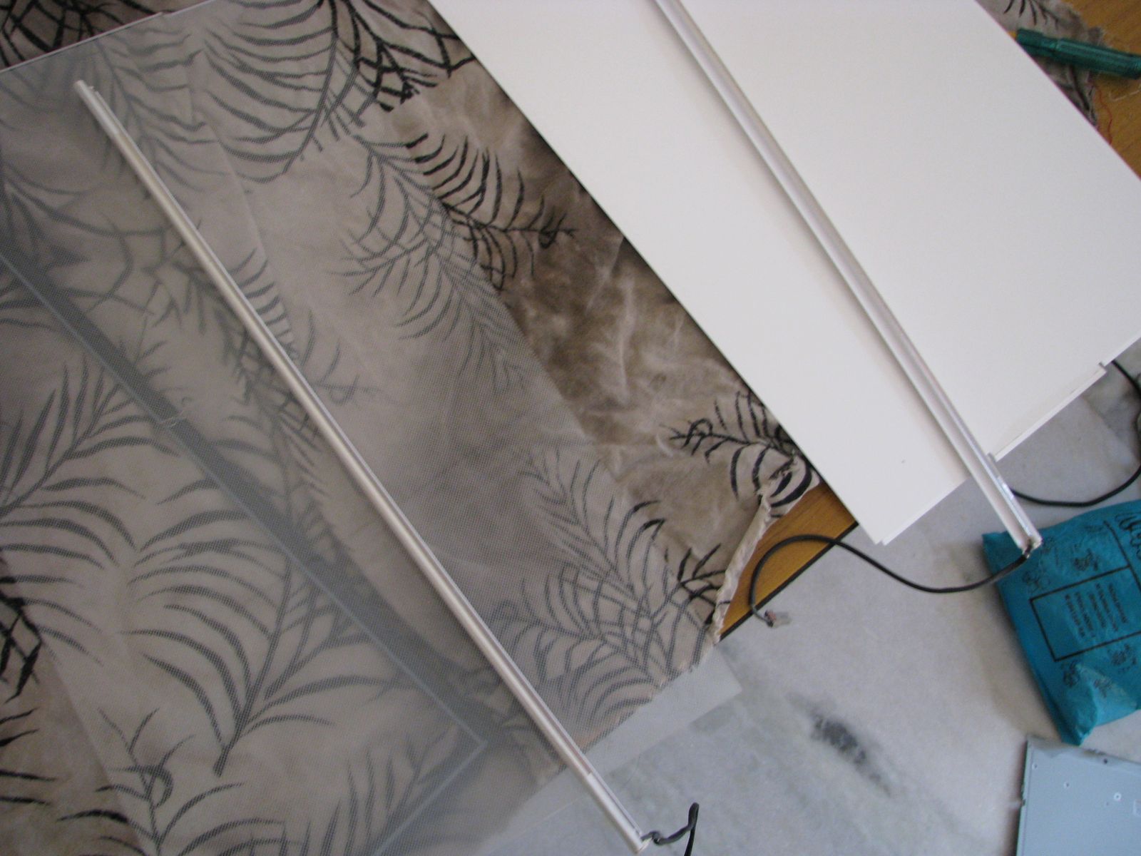
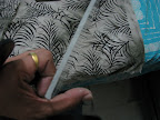
After Sanding and some rubbing with cotton cloth, the edges look much clearer but not transparent. To make them transparent it took a hell lot of work. I put some brasso on edges and rubbed the edges with cotton cloth, the edges are more clear but still not 100% transparent means when I put the screen on printed paper I can recognize the color of the written material from other side but could not read it. The last thing I done is used hair drier to blow hot air over the edges, This made more clearer, still cannot read whole thing written on the paper below other edge but I can recognize some letters. The edges now look like as below, (I am not too good in photography, I will learn after completing this project)
My first step was to make the Edges even for This I used knife to cut out all the protruding edges.
After cutting out edges I filed the edges with a file around 25 frictions at each place.
The first finish edge look somewhat like this.
 |
Once filing on all surfaces is done, I used emery stone then 150 grit sand paper then 1500 grit sand paper.
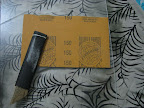 |
After Sanding and some rubbing with cotton cloth, the edges look much clearer but not transparent. To make them transparent it took a hell lot of work. I put some brasso on edges and rubbed the edges with cotton cloth, the edges are more clear but still not 100% transparent means when I put the screen on printed paper I can recognize the color of the written material from other side but could not read it. The last thing I done is used hair drier to blow hot air over the edges, This made more clearer, still cannot read whole thing written on the paper below other edge but I can recognize some letters. The edges now look like as below, (I am not too good in photography, I will learn after completing this project)
 |
Tuesday, October 13, 2009
Material for making MT table.
After a month of study and accumulation I arranged following material for my first MT table.
1) LCD Screen - Moserbear 18.5 in, {6000 INR}.
2) Web Cam - Quantum QHM 500 LM CAMERA, {525 INR}.
3) Acrylic Sheet - 11x18 in,{75 INR}.
[EDIT] the first sheet become unusable as it come exact the size of LCD so will now use it below LCD.
New 12x24 in 6mm sheet {600 INR}.
4) IR LEDs - 50x, 940nm 1.2v 100ma {415 INR]
Resistors - 56ohm 1/8 w for 10x LED series {FREE}
5 ohm for 15x LED series {FREE}
Old Laptop adapter 18.5v 3.6A for LED power supply {From Surplus}.
5) Tools - Sand paper (150 and 1500 mark) {25 INR}
File wide (100 mark) {10 INR}
Brasso {50 INR}
Soldering iron and wires.
Hexa Blade {8 INR}
[EDIT]
6) Compliant surface: Silicon Spray (to be tested)
There are more thing to be arranged, but right now I am starting with this much.
It took 4 hrs distributed in 2 days to file the Acrylic edges, I did not got the clear glass finish but I think it should work.
Will be testing the FTIR without LCD first then will add LCD in weekend.
1) LCD Screen - Moserbear 18.5 in, {6000 INR}.
2) Web Cam - Quantum QHM 500 LM CAMERA, {525 INR}.
3) Acrylic Sheet - 11x18 in,
[EDIT] the first sheet become unusable as it come exact the size of LCD so will now use it below LCD.
New 12x24 in 6mm sheet {600 INR}.
4) IR LEDs - 50x, 940nm 1.2v 100ma {415 INR]
Resistors - 56ohm 1/8 w for 10x LED series {FREE}
5 ohm for 15x LED series {FREE}
Old Laptop adapter 18.5v 3.6A for LED power supply {From Surplus}.
5) Tools - Sand paper (150 and 1500 mark) {25 INR}
File wide (100 mark) {10 INR}
Brasso {50 INR}
Soldering iron and wires.
Hexa Blade {8 INR}
[EDIT]
6) Compliant surface: Silicon Spray (to be tested)
There are more thing to be arranged, but right now I am starting with this much.
It took 4 hrs distributed in 2 days to file the Acrylic edges, I did not got the clear glass finish but I think it should work.
Will be testing the FTIR without LCD first then will add LCD in weekend.
 |
 |
Subscribe to:
Posts (Atom)
